How Do I Reverse Engineer A Part Using Low-Quality 3D Scan Data?
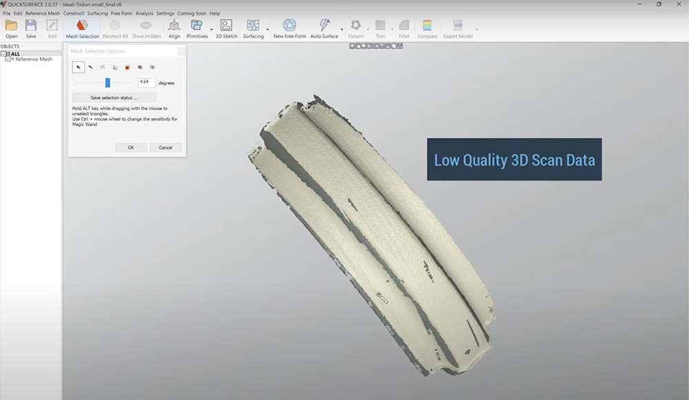
There are times when you only have less than desirable 3D scan data to work with. Unfortunately, that is the only information available for use to reverse engineer a part from scan to CAD.
You might be in this situation because of the following reasons:
- You used a low-cost 3D scanner that is not capable of capturing high-quality scan data.
- You are scanning a shiny, transparent, or dark surface and it wasn’t coated with a 3D scanning spray prior to 3D scanning.
- You were scanning in direct sunlight and your 3D scanner isn’t capable of performing at its optimal performance.
- Time restrictions didn’t permit you to go back to rescan the part in order to get the best results.
- Someone else gave you the scan data for reverse engineering it into a CAD model.

If at all possible, you should always try to get the best scan data you can for reverse engineering as your output is only as good as your input. Getting good source data makes the work ahead that much easier.
However, don’t worry if you weren’t able to get high-quality scan data. Sometimes where or how you obtain the source data is not within your control. In this article, we’ll show you how to reverse engineer with less than desirable 3D scan data.
Video Demonstration
Here’s a video demonstration of the process that shows different ways to go about it. It also includes the thought process one would go about reverse engineering an object from less than desirable 3D scan data.
QUICKSURFACE standalone reverse engineering software was used for this demo.
Takeaway
As you can see in the video, we’ve taken two approaches to reverse engineering from rough 3D scan data.
- Method 1: Reverse engineering as closely to the 3D scan data as possible
- Method 2: Reverse engineering to the design intent (as opposed to just copying the scan data exactly as in Method 1)
The video brings out an important topic, which is the design intent.
Reverse engineering in some ways is like detective work. The scanned data contains clues as to how the original part was designed and functioned. It’s up to you to deconstruct someone else’s work to create your new CAD model.
In the real world, it’s difficult to manufacture products perfectly. Sometimes a physical part might be manufactured slightly off-specs. It might also change from its original design due to normal wear and tear or damage. It’s up to you to do a bit of investigation to understand what the original designer had in mind when designing the original part and then go about making the appropriate modifications as you see fit.
Do you want to:
- (A) Build a new CAD model exactly like the physical object? (as-scanned part)
- (B) Create a new CAD model based on what the original designer had intended? (design intent – what the part should be rather than what we’re seeing from the rough scan data)
- (C) Or, use the scan data to make modifications to the original part? (improved design)
This is why reverse engineering involves a deeper understanding of how the part was originally designed and what you want to do with it (the outcome). It’s about taking a step back and seeing the function versus merely tracing the scan data without putting much thought into it. A lot of times this means that you need to take a methodical approach by analyzing and planning how you want the final model to be—even before you start the reverse engineering process.
Examples of Design Intent
Example 1
From Video: How To Reverse Engineer Less Than Desirable 3D Scan Data
Software: QUICKSURFACE
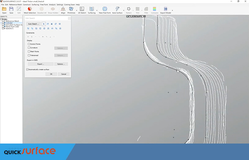
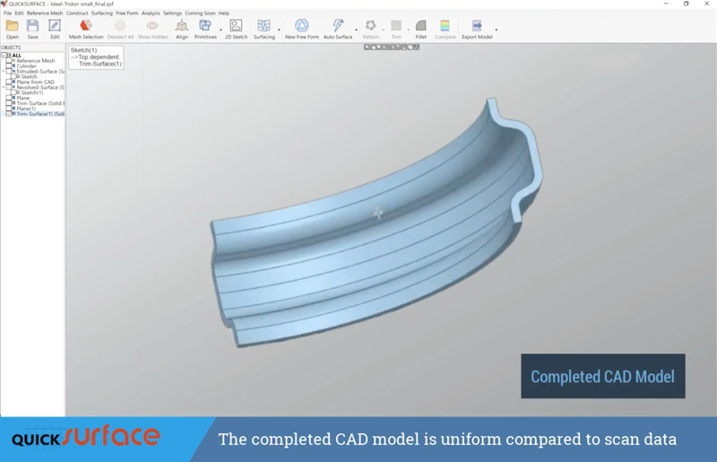
When we were reverse engineering close to the scan data (Method 1), we varied our thickness when sketching the 2D profile which was based exactly on what the scan data showed.
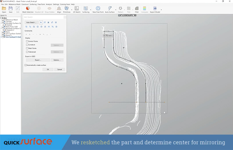
However, in Method 2, we figured that bent sheet metal would be the material that was used to manufacture this part. Consequently, it would make logical sense to make sure our sketch has a consistent thickness all across the part. We also determine the part is symmetrical so the center was found to mirror one side to another.
Final CAD Model
Example 2
From Video: How To Reverse Engineer From Scan to CAD Using Color Texture Information
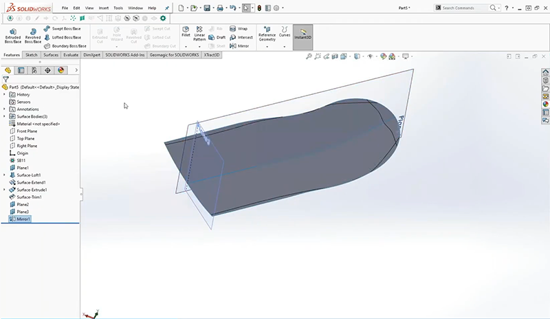
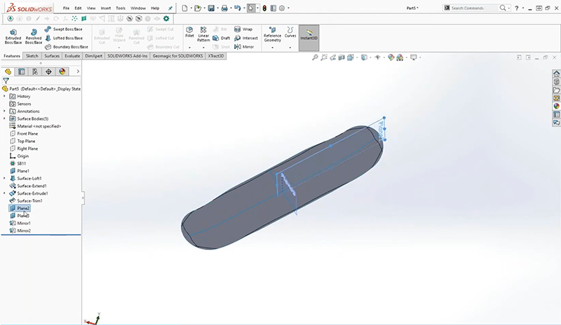
When creating a CAD model of an existing skateboard, we inferred that the part should be symmetrical. As a result, we made the design choice to mirror one side of the design to create the other.
Asking the Right Questions
To make the Scan to CAD process easier, here are some important questions you should ask to make sure the final CAD model you create would truly satisfy your goals:
- Why do you need to create a CAD model from this physical part?
(Purpose – Is it to replicate, design the CAD model true to the original, modify, or improve the part?) - What does this part do?
(Functionality – What or how will it be used?) - Where does the part go?
(Mating Surfaces – What are the critical dimensions/interactions?) - How will this part be made?
(Manufacturing Process -What type of material will be used to manufacture the part?)
Depending on what you want to accomplish, whether you need to replicate the part exactly because you have to manufacture an identical automotive component as a replacement part for a vehicle or you are looking to create a new and improved product, scan data gives you existing knowledge to make inferences. It’s more accurate than designing from scratch or using traditional hand tools, such as calipers, especially for designing organic and complex parts. 3D reverse engineering makes your job much easier.
